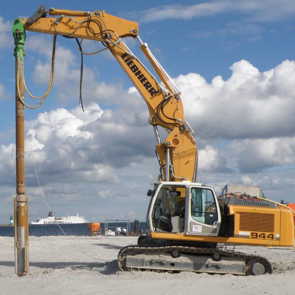
VC STITCHER
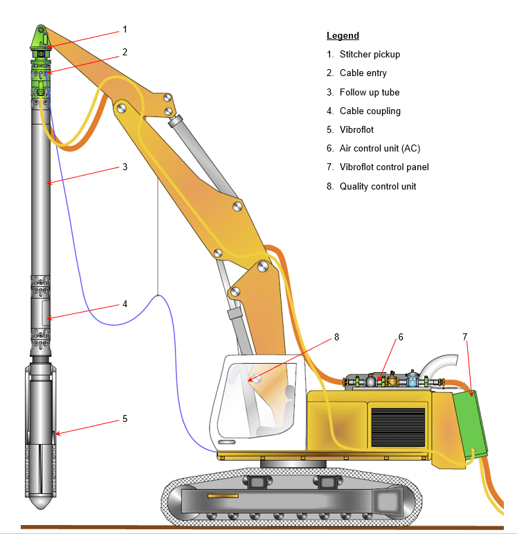
STRUCTURE OF THE PENETRATION UNIT
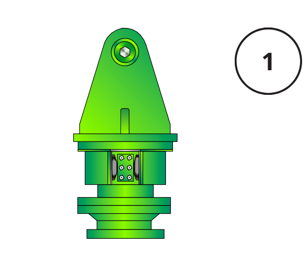
STITCHER PICKUP
The Stitcher pickup is the interface between the penetration unit and the carrier. It is a connection that allows some flexibility and vibration dampening that may be transmitted to the carrier during operations.
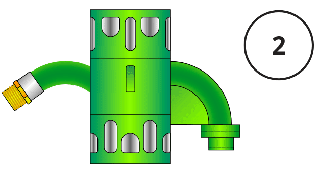
CABLE INLET
The cable inlet is a short tube section that allows the vibroflot electric cable (and air or water) to enter the penetration unit and is sealed against the penetration unit’s internal pressure.
FOLLOW UP TUBE
The follow up tube is available in different lengths and thicknesses to optimize the total length and weight of the penetration unit. The penetration unit can be perfectly matched to both the carrier and working depth
CABLE COUPLING
The cable coupling is used to connect the vibroflot electrical cable to the extension electric cable attached to the control panel. The cable coupling allows for the vibroflot to be exchanged quickly without having to remove the full length of extension cable.
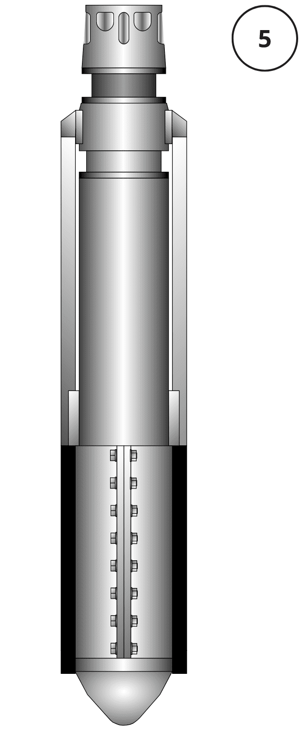
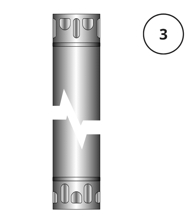
VIBROFLOT
The required vibroflot is attached to the follow up tube completing the penetration unit. Vibro Services caries varied types of vibroflots that allow for individualized performance and optimised operations
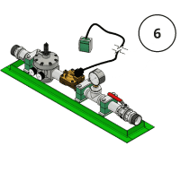
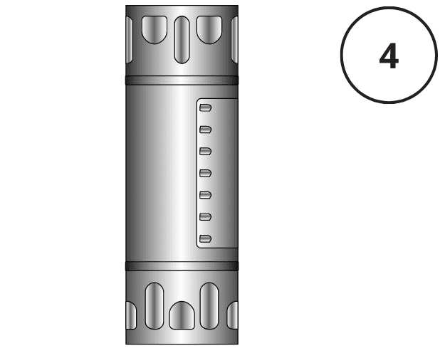
AIR CONTROL UNIT
The air control unit allows for the air system to be optimized to the ground conditions. The air pressure and air volume can be adjusted to minimize disturbance to the soil without compromising the ability for the vibroflot to penetrate to the required depth
CONTROL PANEL
The control panel is used to start or stop the vibroflot as well as protect the vibroflot electric motor from operating outside pre-set values. The vibroflot temperature, voltage and amperage values are monitored by the control panel. Each vibroflot type has a control panel especially designed for its specific values.
QUALITY CONTROL
Vibro Services can supply the DIALOG quality control produced by the company Jean-Lutz. The Digital quality control records the penetration unit operating parameters. The recordable parameters include point number, date, time, vibroflot motor amperage (or hydraulic pressure), gravel volume, penetration depth, and verticality just to name a few. Data transfer is by USB stick or Bluetooth.
DBF Stitcher
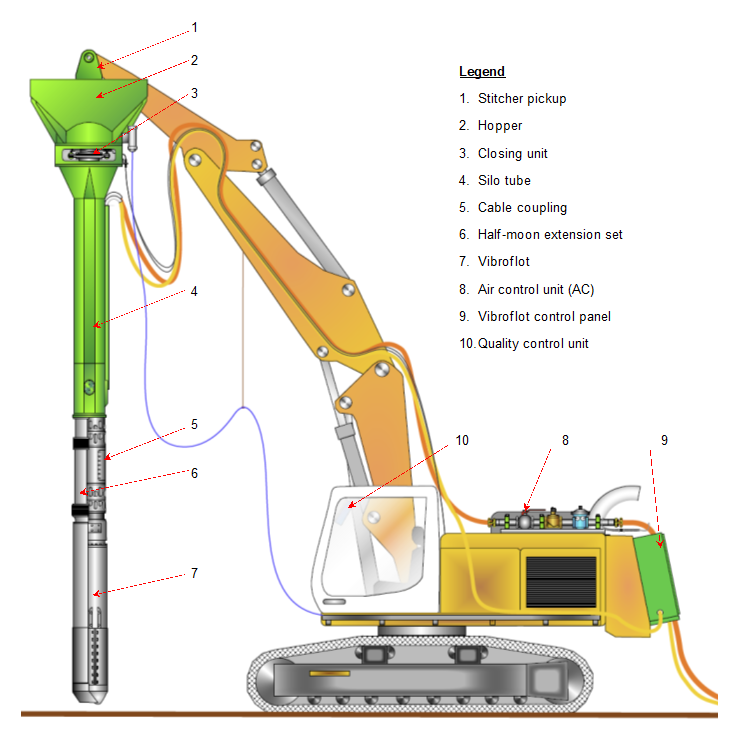
STRUCTURE OF THE PENETRATION UNIT
STITCHER PICKUP
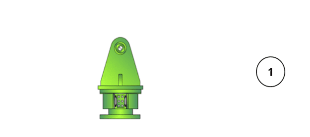
The Stitcher pickup is the interface between the penetration unit and the carrier. It is a connection that allows some flexibility and vibration dampening that may be transmitted to the carrier during operations.
HOPPER
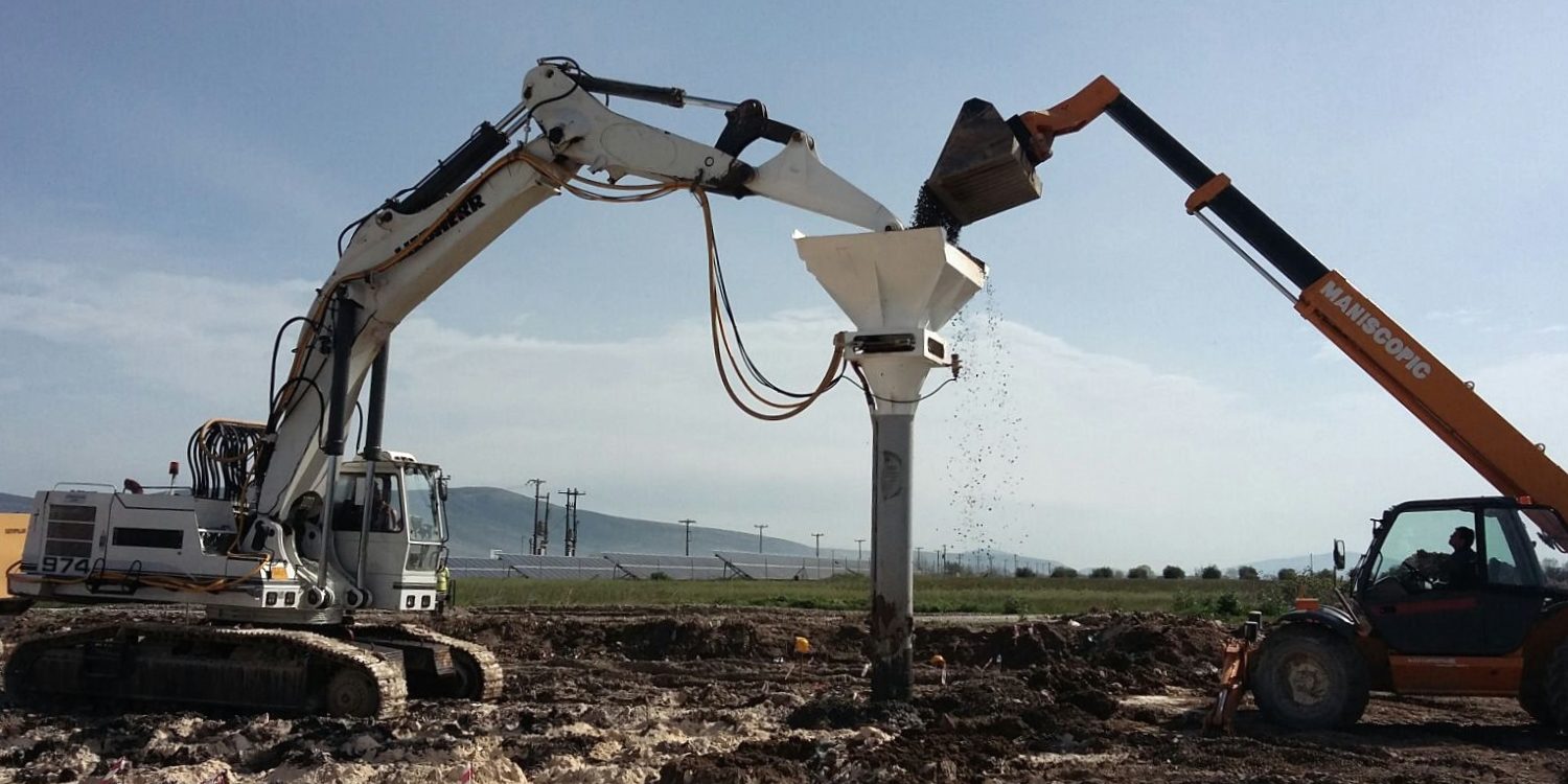
The hopper allows the fill material (gravel, concreate etc.) to be funnelled into the penetration unit via the closing unit
CLOSING UNIT
The closing unit opens and closes allowing the fill material into the system. When closed, the closing unit is airtight retaining the discharge air pressure.
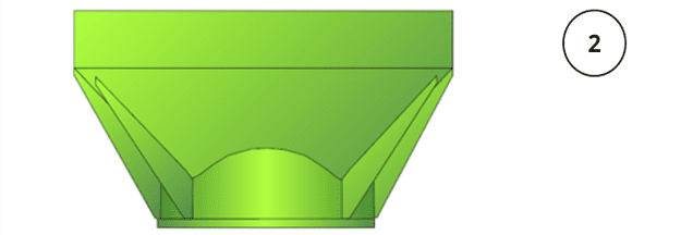
SILO TUBE
The silo tube holds a reserve of material which is used for the column construction. While the material inside the silo tube is being used, a telescopic shovel loader brings the next batch of material ready for use. The silo tube is available in different lengths to optimize the total length and weight of the penetration unit. The penetration unit can be perfectly matched to both the carrier and working depth.
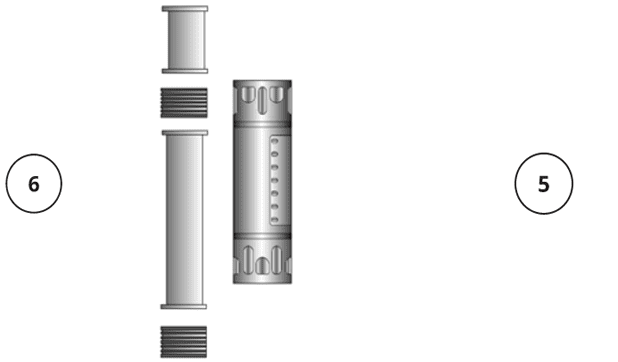
HALF-MOON EXTENSION (set) (5)
The half-moon extension set is a flexible material transfer system that allows material to be transferred from the silo tube which is static to the vibrating vibroflot without transmitting the vibration from the vibroflot into the rest of the system and carrier.
CABLE COUPLING (6)
The cable coupling is used to connect the vibroflot electrical cable to the extension electric cable attached to the control panel. The cable coupling allows for the vibroflot to be exchanged quickly without having to remove the full length of extension cable.
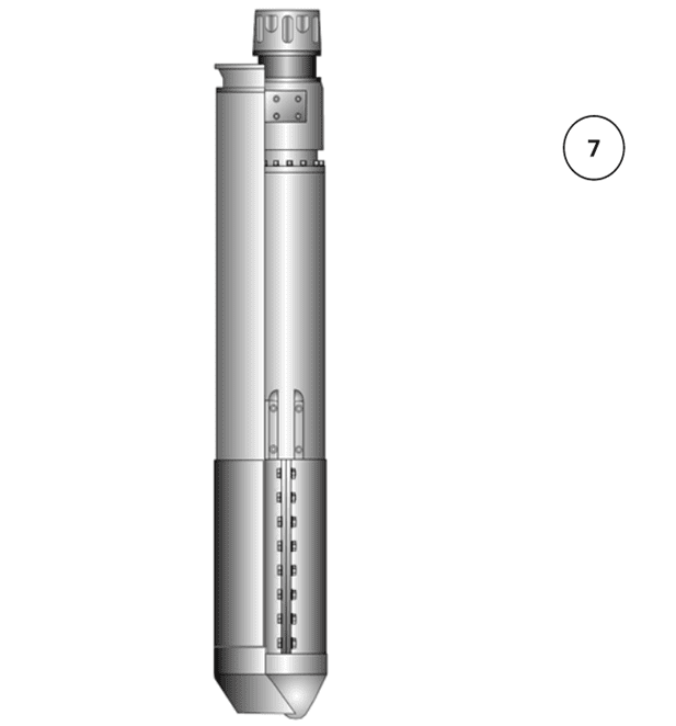
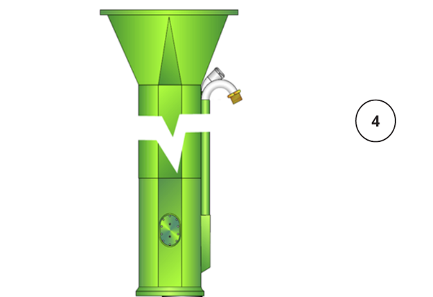
VIBROFLOT
The required vibroflot is attached to the base of the silo tube completing the penetration unit. Vibro Services caries varied types of vibroflots that allows for individualized performance and optimised operations
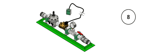
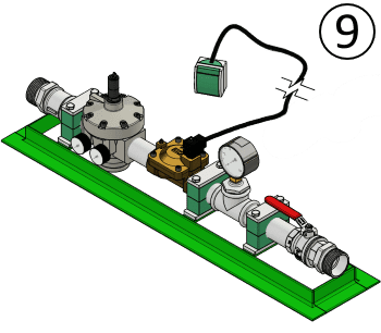
AIR CONTROL UNIT
The air control unit allows for the air system to be optimized to the ground conditions. The air pressure and air volume can be adjusted to minimize disturbance to the soil without compromising the ability for the vibroflot to penetrate to the required depth
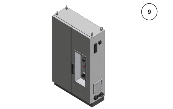
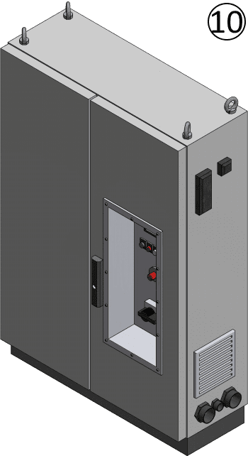
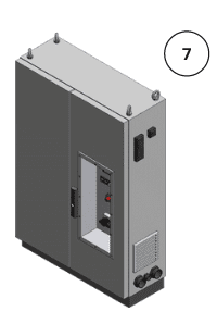
CONTROL PANEL
The control panel is used to start or stop the vibroflot as well as protect the vibroflot electric motor from operating outside pre-set values. The vibroflot temperature, voltage and amperage values are monitored by the control panel. Each vibroflot type has a control panel especially designed for its specific values.
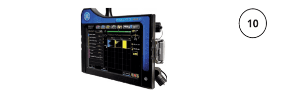
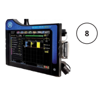
QUALITY CONTROL
Vibro Services can supply the DIALOG quality control produced by the company Jean-Lutz. The Digital quality control records the penetration unit operating parameters. The recordable parameters include point number, date, time, vibroflot motor amperage (or hydraulic pressure), gravel volume, penetration depth, and verticality just to name a few. Data transfer is by USB stick or Bluetooth.
VC Free Hanging
Structure of the penetration unit.
LIFTING HEAD
The lifting head is the interface between the penetration unit and the carrier. It is hinged to allow easy raising and lowering as well as allowing the vibroflot electric cable and the vibroflot nose jet air or water to enter the penetration unit. The connections are sealed against the penetration unit’s internal pressure.
SIDE JET MANIFOLD
The side jet manifold diverts air and water down both sides of the full length of the penetration unit to the side jetting system.
FOLLOW UP TUBE
The follow up tube is available in different lengths and thicknesses to optimize the total length and weight of the penetration unit. The penetration unit can be perfectly matched to both the carrier and working depth.
SIDE JET SYSTEM (4)
The side jetting system is designed to encourage self-feeding of the sand down to the vibroflot compaction zone and in the case of wet top feed stone columns, retain an annular space around the penetration unit for the gravel fill to reach the vibroflot compaction zone and form a stone column.
CABLE COUPLING (5)
The cable coupling is used to connect the vibroflot electrical cable to the extension electric cable attached to the control panel. The cable coupling allows for the vibroflot to be exchanged quickly without having to remove the full length of extension cable.
VIBROFLOT
The required vibroflot is attached to the follow up tube completing the penetration unit. Vibro Services caries varied types of vibroflots that allows for individualized performance and optimised operations
AIR WATER MANIFOLD
Vibro Services has 2 types of air water manifold units. Each allows the water and air to be correctly mixed either to the vibroflot nose and or side jetting system and optimized to the ground conditions and working method. The Semi-automatic air water manifold may be operated from a remote control by the machine operator. The manual system requires an additional operator.
CONTROL PANEL
The control panel is used to start or stop the vibroflot as well as protect the vibroflot electric motor from operating outside pre-set values. The vibroflot temperature, voltage and amperage values are monitored by the control panel. Each vibroflot type has a control panel especially designed for its specific values.
QUALITY CONTROL
Vibro Services can supply the DIALOG quality control produced by the company Jean-Lutz. The Digital quality control records the penetration unit operating parameters. The recordable parameters include point number, date, time, vibroflot motor amperage (or hydraulic pressure), gravel volume, penetration depth, and verticality just to name a few. Data transfer is by USB stick or Bluetooth.
DBF Free-Hanging (V-Rex)
STRUCTURE OF THE PENETRATION UNIT
LIFTING HEAD
The lifting head is the interface between the penetration unit and the carrier. It is hinged to allow easy raising and lowering as well as allowing the vibroflot electric cable and the vibroflot nose jet air or water to enter the penetration unit. The connections are sealed against the penetration unit’s internal pressure.
FORK ASSEMBLY
The fork assembly is a guide that both holds the skip unit in line and assist in the tipping of the fill material during operations.
HOPPER
The hopper is incorporated with tipping hooks that allow the fill material (gravel, concrete etc.) to be tipped into the hopper from the skip and then is funnelled into the penetration unit via the closing unit when required.
CLOSING UNIT
The closing unit opens and closes allowing the fill material into the system. When closed, the closing unit is airtight retaining the discharge air pressure. The V-Rex DBF free hanging unit may be used as a double lock (two closing units) or single lock (one closing unit) system.
SILO TUBE
The silo tube holds a reserve of material which is used for the column construction. While the material inside the silo tube is being use, the skip delivers the next batch of material to the hopper ready for use. The silo tube is available in different lengths to optimize the total length and weight of the penetration unit. The penetration unit can be perfectly matched to both the carrier and working depth.
CABLE COUPLING (6)
The cable coupling is used to connect the vibroflot electrical cable to the extension electric cable attached to the control panel. The cable coupling allows for the vibroflot to be exchanged quickly without having to remove the full length of extension cable.
HALF-MOON EXTENSION (set) (7)
The half-moon extension set is a flexible material transfer system that allows material to be transferred from the silo tube which is static to the vibrating vibroflot without transmitting the vibration from the vibroflot into the rest of the system and carrier.
VIBROFLOT (8)
The required vibroflot is attached to the base of the silo tube completing the penetration unit. Vibro Services caries varied types of vibroflots that allows for individualized performance and optimised operations
SKIP (9)
The skip has a volume capacity of 1m³. The skip is filled using (optimally) a 1m³ shovel loader. The skip is lifted using the crane auxiliary line. The gravel material is tipped into the hopper by the tipping hooks on the hopper.
AIR CONTROL UNIT
The air control unit allows for the air system to be optimized to the ground conditions. The air pressure and air volume can be adjusted to minimize disturbance to the soil without compromising the ability for the vibroflot to penetrate to the required depth.
CONTROL PANEL
The control panel is used to start or stop the vibroflot as well as protect the vibroflot electric motor from operating outside pre-set values. The vibroflot temperature, voltage and amperage values are monitored by the control panel. Each vibroflot type has a control panel especially designed for its specific values.
QUALITY CONTROL
Vibro Services can supply the DIALOG quality control produced by the company Jean-Lutz. The Digital quality control records the penetration unit operating parameters. The recordable parameters include point number, date, time, vibroflot motor amperage (or hydraulic pressure), gravel volume, penetration depth, and verticality just to name a few. Data transfer is by USB stick or Bluetooth.